| Projects |
| News of a site |
| Links |
|
Refresh: 3 July, 2003 |
New technology of with short / vertical take-off and landing (STOL / VTOL) airplanes development(improvement on lift creation basis by "vortical" method)The successful realization of this technology will permit to decrease the air transportation cost and also the requirements to the airports and places of their location. The military aviation may receive the new possibility during military operations. ContentsSummary Summary (back to contents)The airplanes take-off and landing characteristics improvement is one of the required ways of the aviation development as these characteristics have the decisive influence on the following:
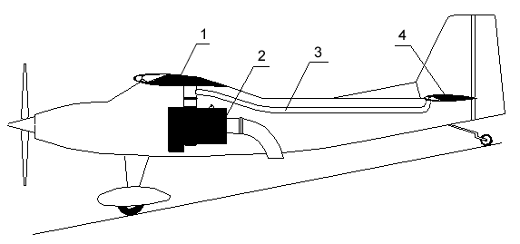
So the works are carrying out actively on the take-off and landing characteristics improvement - airplanes development with short take-off and landing (STOL) and like ideal airplanes with vertical take-off and landing (VTOL) - by many producers of the aviation products of the domestic and foreign scientific and research institutes and companies. But the more effective way from the known ones of ensuring the short take-off and landing (i.e. connected with development of the additional lift) and all ways of ensuring the vertical take-off and landing due to the low weight efficiency, arrangement difficulties, high level of noise produced on surroundings, high level of runway erosion etc. did not find the wide use and are used only for the military airplanes (like Harrier, Osprey, Yakovlev-38 and 141 etc.). On principle new "vortex" method of lift development is suggested to use in this project for STOL / VTOL airplanes development. Its realization is confirmed the mathematical simulation and real experiments in Zhukovsky Central Aerodynamic Institute by Zhukovsky - (Russian Federation, Zhukovsky). STOL / VTOL airplanes demonstration stand article development is proposed as a final product for demonstration of technology development possibility. This technology development perspective is connected with its use for airplanes of the different meaning which possess the different velocities of the cruise flight, take-off mass and dimensions. And its also permits to make the quantitative jump in the airplanes take-off and landing characteristics improvement inside the existing technologies, arrangement and design decisions without development of the new materials and fuels. Description (back to contents)The detailed essence of the "vortical" method for the lift creation is given in the RF patents No. 2116224 (priority on 08.04.1994, registration on 27.07.1998) and No. 2144886 (priority on 02.03.1998, registration on 27.01.2000) and also in statement No. РСТ/RU 99/00052. As to the demonstration test article of the airplane with the short runway/vertical take-off and landing (see Fig.1) it is foreseen to re-equip the airplane of the traditional structure with wing and horizontal tail developed for the "vortical" method for the lift creation and also with the special power plant for the compressed air generation and its supply through pipelines to wing and horizontal tail.
Wing (see Fig. 1…4) is equipped with the turn module located along wing span in the wing front part and flap aileron (flaperon) with the upper flap located along wing span in the wing rear part. Then turn module consists of the nose flap, tank for the air supply and channel connected the tank with upper surface of wing.
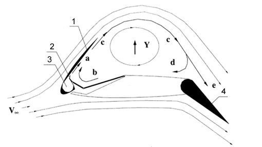
The wing configuration for the flight mode with the small velocities is given in Fig. 2. The air, taken from the special power plant compressor, is sent into the tank. The ejected jet "a", coming out from the channel along the nose flap of the turn module installed under the angle to the upper surface of wing, is mixed intensively with the air, located in space between the nose flap and upper surface of wing, and forms the ejected jet "b" and flat jet "c". At ejection of jet "b" the full pressure of the air is decreased in space between jet "c" and upper surface of wing that brings to inclination of jet "c" in direction of the upper surface of wing and decreasing of the full pressure dropping in it. In this case, one part of jet "c", like jet "d", is returned along the upper surface of wing into the ejected area of ejected jet "a" and other part, like jet "e", is gone with the flow flowed over the wing. During movement of jet "d" along the upper surface of wing into the ejected area of ejected jet "a" its velocity is increased and its static pressure is decreased. The flaperon serves like flap increasing the wing profile curvature. The increase of lift "Y" is stipulated by increasing the curvature and relative thickness of the new formed "liquid" profile of wing and decreasing the static pressure in jet "d".
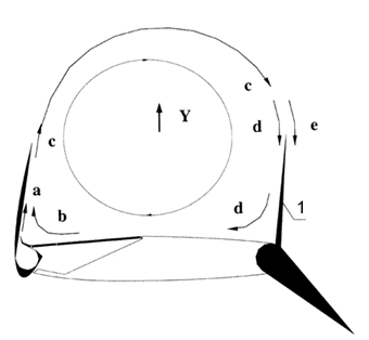
The wing configuration in mode of the vertical take-off and landing is given in Fig. 3. Here for ensuring of the maximum angles of ejection of jet "c" the area of the return flow is separated from atmosphere by the upper flap of flaperon and lift "Y" is formed due to difference of the static pressure in jet "d", acted on the upper surface of wing, and full atmospheric pressure, acted on the lower surface of wing.
The wing configuration (Fig. 4) in mode of the cruise flight - turn module is located in packed position and flaperon is serves like aileron controlling the flow, flowed over the wing. The structure of the horizontal tail and its functioning are analogous ones like for the wing. Demonstration of activity of a wing of an airplane STOL (back to contents)(Macromedia
Flash) Work carrying out (back to contents)The mathematical simulation and set of the wind-tunnel tests of the wing real models are carried out for studying the lift forming process. Mathematical simulationThe main elements of the lift forming process for wing, staying in the air flow, are confirmed during the mathematical simulation, including the following:
Experimental simulationThe wing model wind-tunnel tests in confirmed the technical realization of the vertical take-off and landing mode with using the wing, staying in the still air conditions, including the following:
Advantages (back to contents)The investigations, carried out up to day, permit to make a conclusion about the following advantages of the suggested technology of the lift creation in comparison with the known ones in use for the airplanes take-off and landing characteristics improvement:
Use perspective (back to contents)The
suggested technology can be used for airplanes of the different
meaning (i.e. general, civil, main, military etc.) for the flight
characteristics improvement for the small velocities (take-off,
landing and maneuvering). The suggested technology realization may influence essentially on the aviation development and will permit the following: Transportation aviation:
Military aviation:
Works plan for project realization (back to contents)The phase works realization for the project fulfillment is suggested for decreasing the risks, people and hardware expenses. Laboratory testsThe laboratory test purpose is development of the initial data optimal parameters selection methods for designing and engineering the full scale airplane (requirements for power plant, flight control units etc.). Demonstration test article developmentThe
demonstration test article development purpose is to demonstrate
the possibilities of the "vortical" method for the lift
creation and forming the initial data confirmed during the full-scale
tests of the real article for the further integration. Stand testsThe
stand test purpose is confirmation of the design take-off and landing
characteristics during the full-scale tests and demonstration of
the technology possibilities.
The
ground tests carrying out are possible at the manufacturer's plant
as it does not require the using and development of the expensive
special equipment and rooms. Links to other sites devoted STOL and VTOL (back to contents)
|


